Gear Handle Last update: Apr. 2015
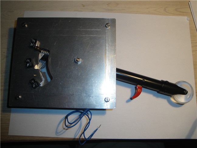
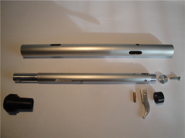
Gear handle before assembly.
Materials: ø16/14mm alu. tube, ø25/22 tube with nylon bearings, ø5 and ø6 brass
bar, 1,5 and 2 mm alu. plate, 1mm brass plate and acrylic for the wheel
The trigger limit the normal pull distance to about 8 mm.
If the trigger is pulled you get additional 7 mm and the lock pawl can be
override. (if solenoid fail)
Later I have change the construction (see last picture on the page).
Handle and lock mechanism.
When the plane is in the air the solenoid is powered and the lock pawl will
release.
The solenoid is a 12V 1A with return spring. Part name
F0837L-12V from www.transmotec.com
You can buy solenoids much cheaper at eBay but I have read about
overheating problems with discount solenoids under continued power
conditions.
Unit ready for wireing.
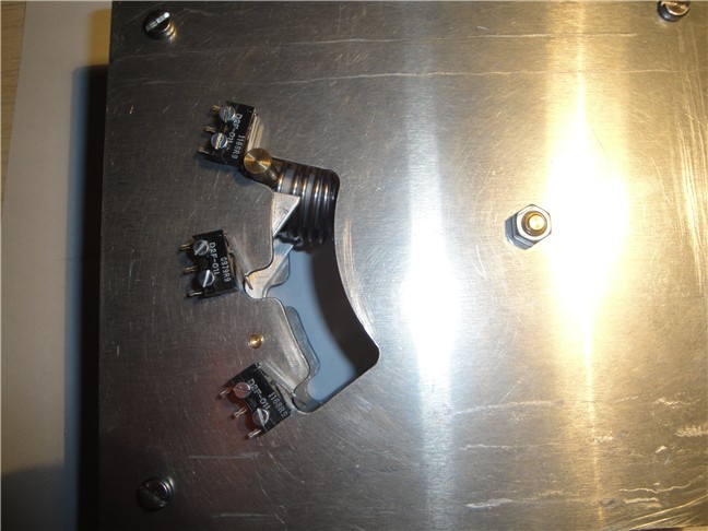
My new unit has 3 micro switches in fact ProSim also
support gear OFF position.
Notice the lock pawl which secure the handle not can be moved when the
aircraft is on ground.
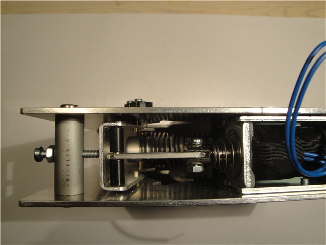
From underside. Solenoid connected to the lock
pawl.
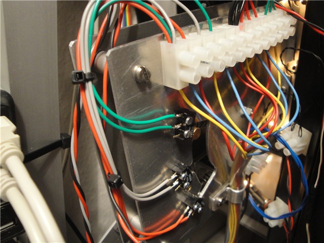
Gear handle unit on its place in the simulator. Most of
the wires are for the gear light indicators.
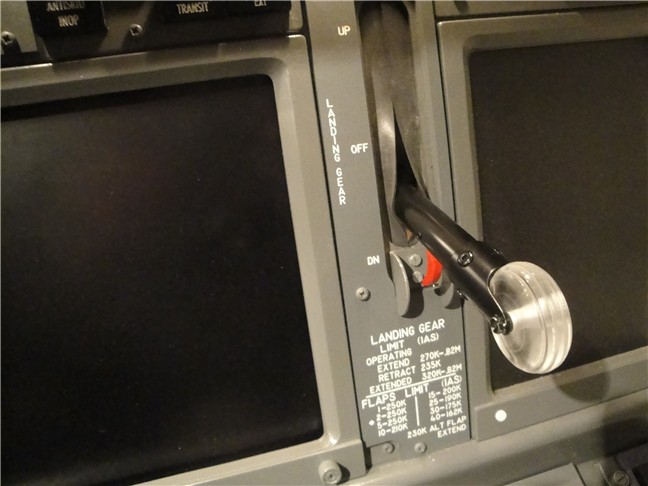
And finally the handle seen from the MIP front.
New parts for my Landing Gear Handle ver.3.
Short time after my new landing gear handle (ver.2) was finished I saw a
website www.B747-400.net with
many pictures of a dismounted real Boeing gear handle. I could see the lock
override construction is a more simple and robust construction than mine so
I have made some new parts.